Modern notebooks do not come anymore with parallel ports. If you are luck and have a docking station, perhaps. Otherwise no more fun with LPT interfacing alas.
So I had a look at USB or Cardbus/PCMCIA solutions.
Do not bother with the USB to LPT adapters. Those are capable of driving a printer, but the interface as is required for the programming here is not there.
There are many Cardbus Parallel port adapters and most also do not work as I want.
I did find one, and it works fine. It is the Delock PCMCIA Cardbus 1 x Parallel adapter.
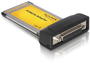
Ofcourse it has the big DB25 pin connector as you can see, it is really standard.
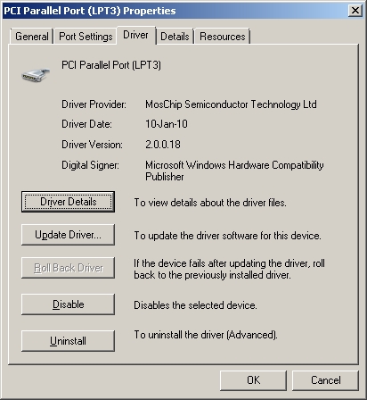
Drivers are either found at the driver cd or (more uptodate) at Delock’s website. Windows 7 drivers are installed automatically. As you can see, the card is based on a MosChip IC.
Now not everything is simple as with the oldfashioned parallel port.
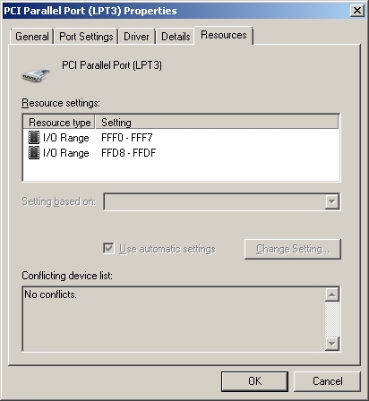
As you can see in the Properties tab (Device Manager shows this) for this instance it is LPT3 and the I/O range is starting at FFF0. Depending on (I really dont have a clue!) it can also be other I/O resource addresses and/or LPT port numbers. It is the same after every reboot, so it is only once determined.
Substitute this in your program (and remove the sanity checks if any for valid ports).
My tests has shown this to work as a standard LPT port. It is a bit slower alas.
Checks maximum speed that can be obtained by reading from the LPT port.
5,000,000 bytes are read into a buffer in a loop as fast as possible.
Time elapsed and obtained speed of sampling are reported.
Requires port95nt.exe (DLPORTIO) on Windows 32 bit, see here for 64 bit.
Run it multipe time to get an impression of the accuracy that can be obtained, with the rest of Windows interfering. The code contains thread and process priority raised to as high levels as possible, the influence of this is minor but visible.
Test results so far:
– Pentium IV notebook Windows 98 Se 650 kHz (648-652)
– Gateway 7 (Pentium III 450) 680 kHz (678-681)
– DELL Optiplex Dual Core 5400 2.3 GHz 720 kHz (719-721)
It seems that the parallel port architecture + DLPORTIO limits the speed of sampling.
Program + source of LPT Speed (Delphi 7).
The procedure doing the sampling is shown here. Note that the port has to be set to input, see the parallel port page for information on that.
procedure TLPTSpeed.bcaptureClick(Sender: TObject);

var
  start,stop, freq:int64;
  elapsed : extended ;
  buffercount :cardinal ;

begin
  QueryPerformanceFrequency(freq); {Get frequency}

  buffercount := 1 ;
  screen.cursor:=crHourGlass; {show busy cursor}

  {collect data }
  SetPriorityClass(GetCurrentProcess, REALTIME_PRIORITY_CLASS   );
  SetThreadPriority( GetCurrentThread, THREAD_PRIORITY_TIME_CRITICAL  );
  QueryPerformanceCounter(start); {Get initial count}
  repeat
    buffer[buffercount] := DlPortReadPortUchar($378) ;
    buffercount := buffercount + 1 ;
  until buffercount = bufferlen ;
  QueryPerformanceCounter(stop);

  SetPriorityClass( GetCurrentProcess, NORMAL_PRIORITY_CLASS );
  SetThreadPriority( GetCurrentThread, THREAD_PRIORITY_NORMAL  );
    screen.cursor:=crDefault;  {show normal cursor}

  { report }
  elapsed := ((stop - start) * 1000) / freq  ;
  log.lines.add(FormatFloat('0.00',(elapsed))+ ' ms') ;
  elapsed := bufferlen /  (elapsed)      ;
  log.lines.add('Frequency = ' +  FormatFloat('0.00',elapsed) + 'kHz') ;
end;
An 8 relay card for the parallel port. This is a better type, since it has its own buffer, so you can detach the PC after setting/clearing the relays. Most parallel port relay card do not have a buffer, so they are easy to program, just write a value to the data port.
With the TESTLPT program I discovered this card behaves like a printer:
– set the wanted setting on the data pins
– change the strobe output for a short period
– hear the relays click to the requested state

To really test this nice piece of hardware I wrote a barebones program. It can turn on and off each relay, or all relay on and off with one click.
Ofcourse a real application requires a scheduler with programmable activities. Maybe I will add that later, this is enough to test the device and my skills to program it myself.
The LPT Relay program as Windows installable.
The sources of LPT Relay
Screenshot:

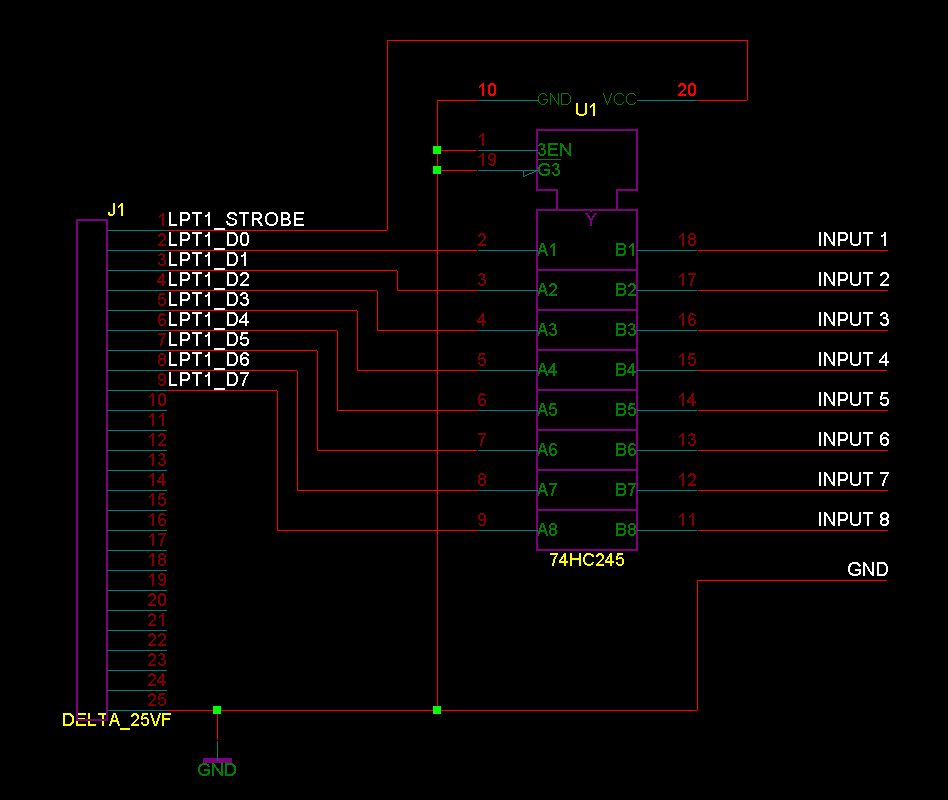
Original circuit diagram
The TFLA is a 8 port logic analyzer. Connected to the parallel port of a fast PC, the sampling rate can reach 1 MHz, And that makes it usable for my 6502 systems! Also perfect to analyze serial transmission.
I have built the TFLA, the acronym for The Fabulous Logic Analyzer.
Not my own design, here is the original design, here the Windows program and here the source and design.
The TFLA is a 8 port logic analyzer. Connected to the parallel port of a fast PC, the sampling rate can reach 1 MHz, And that makes it usable for my 6502 systems! Also perfect to analyze serial transmission.
I made some changes to the original design:
– Between the parallel port and the output of the buffer I added 1 K resistors. To protect PC ports that are not bidirectional.
– Added 100 ohm resistors between the input and the buffer. To protect the buffer.
– Added 10k ohm resistors to ground at the input of the buffer. This makes sure an unconnected input is at null level.
– Power for the buffer IC is taken from the USB port. Also this +5V is brought to the outside, enough to provide power for experiments.
– The buffer is a 74HCT245, a perfect low power high impedance buffer IC.
– Connection between the TFLA and the parallel port via a Centronics connector (from an old printer!) and a standard printer cable.
– The connectors for the logic input signals are from Conrad (2.6 mm) 730599 – 89 and 733628 – 89 (PCB bus).
– The clips are from dealextreme.com
– The simple circuit is built on a strip-board.
Here are the photos:


To be able to read and write from the PC ports like the parallel port, one needs to understand it workings. And a way to circumvent the operating system from accessing directly the ports.
 This document describers all you need to know about the parallel port in bidirectional mode.
Elektor magazine published an article on testing the parallel port with a device showing with LEDs the state of every pin of the port. I have build one and its very handy testing devices and in general the elementary programs for the parallel port.

 DLPORTIO is a driver and API to read and write ports in a PC under Windows 95/98/2000/XP.
DLPORTIO.PAS is a unit for Delphi/FreePascal with the API to DLPORTIO. See this page for Windows 64!
To combine all this knowledge and get started again with Delphi I have written a simple but effective program, TESTLPT, to read and write all ports relevant for the parallel port.
Here you find TESTLPT, complete with DLPORTIO , all automatically installed in Windows.
Sources of TESTLPT